
1-877-795-2278 | info@aircraftspruce.ca
Aircraft Spruce Canada
Brantford, ON Canada
Corona, CA | Peachtree City, GA
Chicago, IL | Wasilla, AK
Aircraft Spruce Canada
Brantford, ON Canada
Corona, CA | Peachtree City, GA
Chicago, IL | Wasilla, AK
 Aircraft Spruce Canada
- Wishlists
- 1-877-795-2278
- Contact Us

FREE SHIPPING ON ORDERS OVER $699 (SOME EXCLUSIONS APPLY) | 877-795-2278
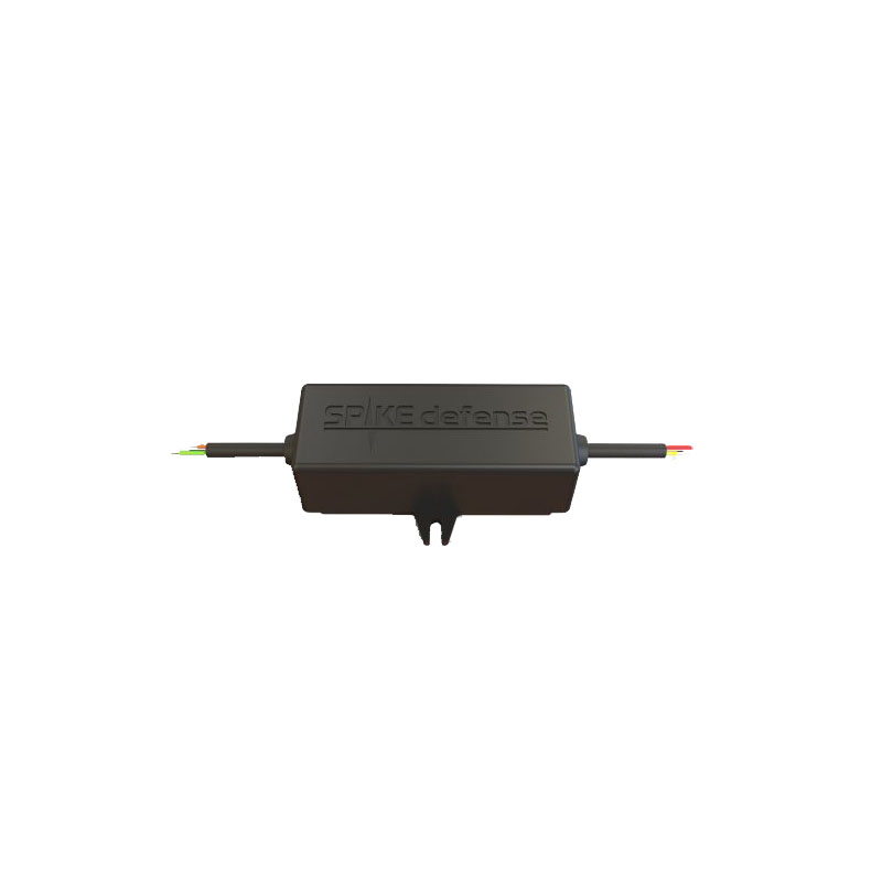

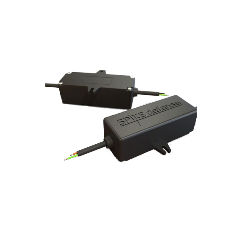
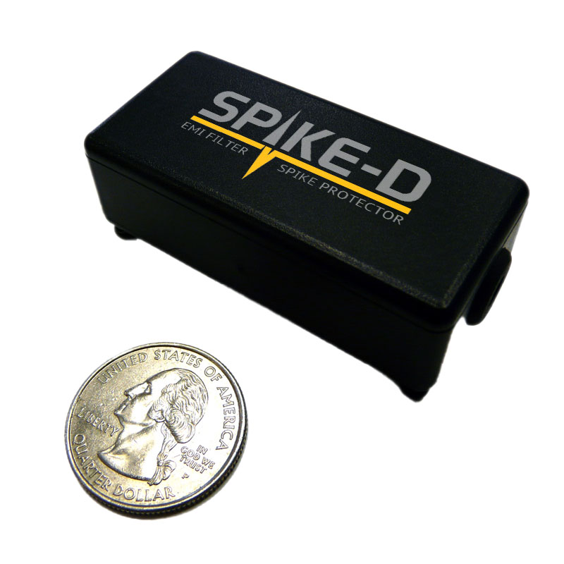

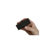
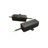
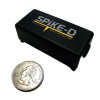


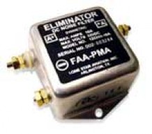
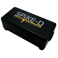
Aveo 2-In-1 Emi / Overvoltage Super Spike-Sd Module
$398.00/Each
Part# 11-14461
MFR Model# AVE-OVUBWB28C-16A
MFR Model# AVE-OVUBWB28C-16A
Overview
|
Electro Magnetic Interference (EMI) is a natural byproduct of all aviation anti-collision strobe systems, both old and new. It is created and radiated when strobe systems suddenly turn electricity into light pulses, and sometimes can be annoyingly detected in intercoms and communication radios as audio noise every time the strobes activate. Aveo Engineering designs and builds extremely quiet LED strobe systems, as evidenced by our beacons and wingtip units. So much so that Aveo products are widely used in military UAVs, where low EMI is an absolute requirement. Anything that could interfere with operational telemetry is simply not tolerated. In aviation, there is no such thing as good EMI, no matter how small. Aveo has taken the extra step to create the Super Spike-SD series of in-line EMI filters. These small, inexpensive units are extremely effective in greatly attenuating residual EMI found in avionics installations. Spectrum analyzer photos which can be viewed on the Aveo website: https://www.aveoengineering.com/spike-sd/ show just how effective the Spike-SD filters are. (Frequency range of the analyzer photos depicted is 300kHz 2MHz, which corresponds to DO-160 Chapter 21, Emission of Radio Frequency Energy.)
IMPORTANT NOTE: Hercules Drop-In with the lower voltage range of 9-18VDC has only one input and cannot be used with super Spike-SD, as current consumption is 12.6A at 9VDC, which exceeds 8A per channel. Samson Drop-In also has only one input and cannot be used with super Spike-SD, as current consumption is 11.1A at 18VDC, which exceeds 8A per channel. |
Specifications
| Unit characteristics: | 2 channels Overvoltage Protection |
|---|---|
| Dimensions: | 80.4 mm x 31.4 mm x 23 mm / 3.16" x 1.24" x 0.9" |
| Voltage range: | 9-36VDC |
| Voltage protection: | - Transcend voltage: 150V at 2second max, both polarities; - Under-voltage protection lockout: 7.4V; - Under-voltage protection relies: 8.2V; - Over-voltage protection lockout: 44.3V; - Over-voltage protection relies: 41.6V; - Reverse connection protection: 80V, not less; |
| Over current protection: | 9A, not less |
| Performance: | - Filtration DO-160G, chapter 21, Emission of Radio Frequency Energy: More than 10dB; - Output current, not less than: Steady: 8A per channel; Pulse 1/3: 9A per channel; - Output power, not less than: Steady: 8A at 9-36VDC per channel; Pulse 1/3: 9A at 9-36VDC per channel; - Input power, not more than: Steady: 8A at 9-36VDC per channel; Pulse 1/3: 9A at 9-36VDC per channel; Warm up time: 0.5sec Ambient temperature: -40°C - +85°C Overheat protection: +85°C |
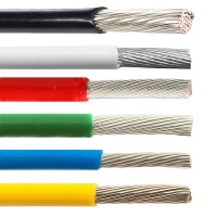
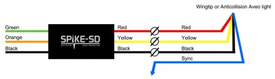
| Wiring: | a. wire type: FEP High Temperature teflon wire, 16 AWG b. wire length: min. 10 inch (280mm) Wire color code: 1. Input, power supply side: a. 16AWG Green +9-36V, first channel input b. 16AWG Orange +9-36V, second channel input c. 16AWG Black Common return VRTN to power supply for first and second channel 2. Output, light side: a. 16AWG Red +9-36V, first channel output b. 16AWG Yellow +9-36V, second channel output c. 16AWG Black GND light **Please, do not connect black wires from input and output together. |
Documents
FAQs
What can one do about radiated noise?Radiated noise can be produced by power leads and circuit boards when there is a sudden demand for current the power leads can become a transmission line for a few milliseconds/nanoseconds, causing the noise. Unshielded twisted pair (UTP) wiring is a likely candidate for noise pickup. This is especially likely if there is an inadequate ground, or the cable is routed close to a noise source. Using shielded cabling helps in that situation, and grounding any coax that is adjacent. The Super Spike SD does address radiated noise as well as inducted RFI.
How does one address inducted noise?
The Super Spike-SD addresses inducted RFI noise. EMI at lower frequencies is caused by conduction (physical contact of wiring); at higher frequencies it is derived from induction (no physical contact). Conducted noise has a relatively clear path, whereas inducted noise is radiated by traveling through space. Conducted noise can still enter the system through the ground. If the ground wire contains electrical signals, they do not mysteriously disappear; they travel the path of least resistance and sometimes return to their point of origina device, ground, or even earth.
It should be noted that advances in technology will certainly increase inducted noise over which the pilot will have no control, unlike adding equipment and being able to physically avoid radiated noise. There are intentional radiator devices such as radio and television transmitters, citizens band and amateur radio transceivers, cellular telephones, radar and electronic navigation systems etc., wherever RF signals are being deliberately emitted. There are also natural sources of EMI such as lightning, cosmic radiation, solar radiation, and nuclear decay. Adding a Super Spike-SD now is part of a future protection plan against future inducted noise interference.
If the noise is generated by an antenna, is there a solution?
Antenna generated noise can typically be addressed with line-of-sight alterations and physically distancing the antenna communications lead away from the lighting leads. Adding ferrite chokes are also to an extent useful, with placement usually set by trial and error testing.
How can I figure out where the noise is coming from?
To isolate wiring or grounding as the problem, bench test the light by removing it from plane and hooking it up to a power supply on a bench and if the same noise can be heard on a handheld aviation radio, then it would indicate the noise is being put out over the air vs. any wiring as there is no shared wiring/grounding when using the hand held radio.
You can also perform the same test with a handheld with manual squelch set just past being off, and when placing the rubber ducky antenna right up against the light, see if squelch will be broken in unison with the strobe flash. When moving the handheld away from the light, past a few inches, the strobe flash should not break squelch. If the noise you experience with your handheld can be heard even when standing a few feet away from the light (with the handheld), this suggests that it is caused by over the air interference vs. wiring/ground, see if you can make the noise disappear by moving the light so that it's "below" line of sight of the antenna.
The two sources of this type of noise are either inducted or radiated. Power leads to the light can be a source of radiated noise when there's a sudden demand for current, and the power wire becomes a brief transmission source for a few milliseconds. This can occur if that wire happens to be physically located right next to your comm antenna or an ungrounded coax. Installation of a ferrite choke on the wiring just before each light may eliminate the issue. Or it may require Aveos Spike.
If you can temporarily power up the light from a different power source than the aircraft with an isolated ground, and you still have the noise, then neither the chokes nor Aveos Spike will help. Then the solution is to increase the distance or insert some blockage/barrier between the lights and the radios you could also insert a brass orcopper barrier to block the interferences.
Q&A
Please note, Aircraft Spruce Canada's personnel are not certified aircraft mechanics and can only provide general support and ideas, which should not be relied upon or implemented in lieu of consulting an A&P or other qualified technician. Aircraft Spruce Canada assumes no responsibility or liability for any issue or problem which may arise from any repair, modification or other work done from this knowledge base. Any product eligibility information provided here is based on general application guides and we recommend always referring to your specific aircraft parts manual, the parts manufacturer or consulting with a qualified mechanic.